
The featured image illustrates the product or installation context; the supplied configuration is confirmed for each order.
A cable tray material list often starts with metres of straight tray. That is only one part of the route. Changes of direction, branches, level changes and equipment entries create accessory requirements that can be missed when the list is prepared from a total length alone.
Work through the route one section at a time
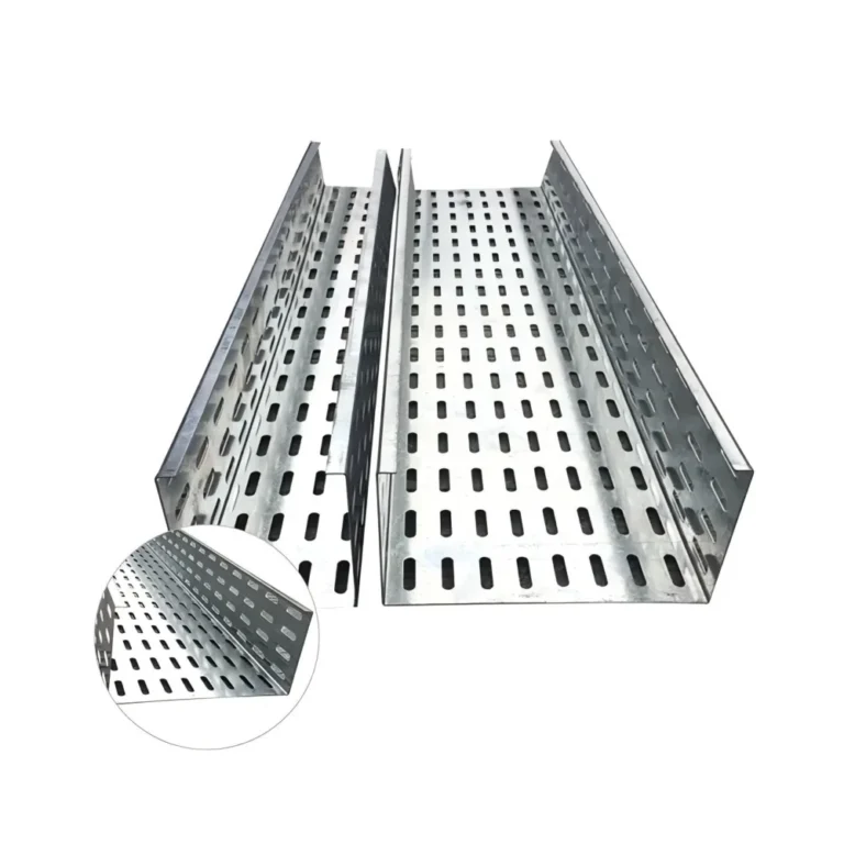
Assign a reference to each route or zone and note the tray type, width, depth, material and finish. Mark the drawing revision used for the take-off. Then follow the route from its starting point to each destination, recording the fittings at every change.
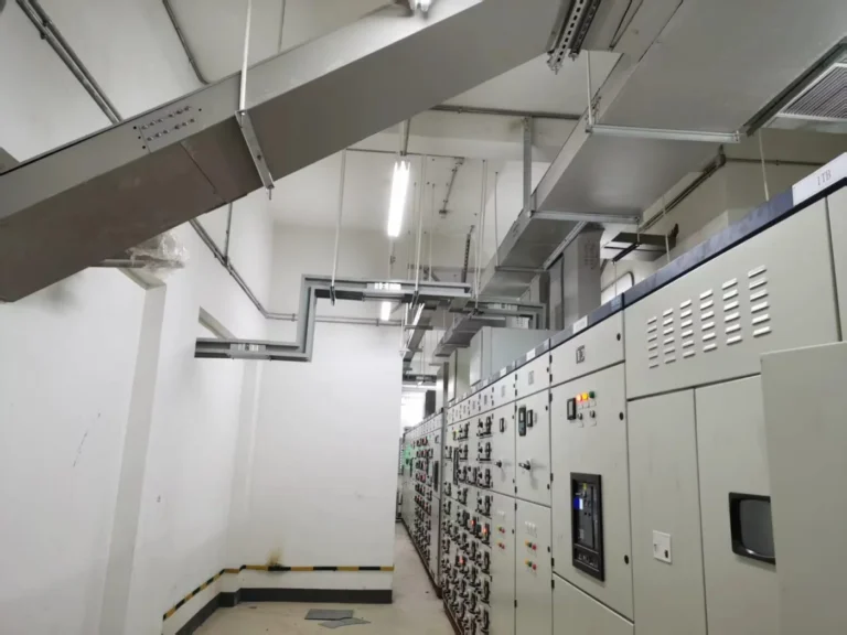
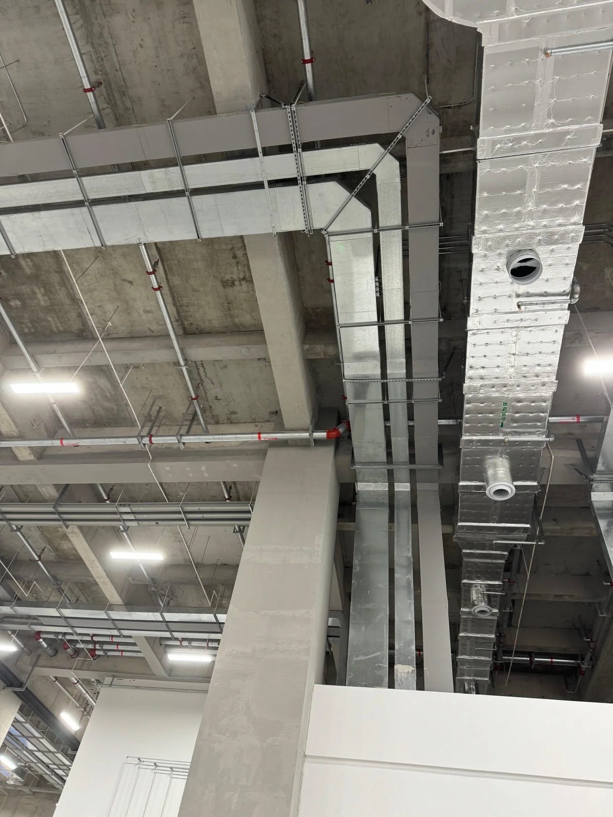
Keep horizontal changes separate from vertical ones. Identify where a branch needs a tee or cross, where the width changes, and where the route enters equipment. A photograph can help explain the installation context, but the quantity schedule should come from controlled drawings and verified dimensions.
Use an accessory schedule alongside straight lengths
- Direction changes: bends and risers with the required geometry.
- Branches: tees or crosses linked to their drawing locations.
- Transitions: reducers and equipment-entry details.
- Connections: couplers, fixings and specified continuity provisions.
- Protection and segregation: covers or partitions where required.
- Support interfaces: brackets, hangers and clamps within the agreed supply scope.
State the unit for every line. Metres, individual pieces, sets and packs are not interchangeable. If a fitting is sold as a kit, ask what the kit contains before adding separate fasteners to the list.
Confirm support arrangements for the selected system
Support planning depends on the system, loading and route. Eaton’s cable tray guidance treats fittings and their support locations explicitly, illustrating why support details should be reviewed with the chosen tray arrangement. See Eaton’s cable management catalogue for manufacturer-specific examples.
Use the selected manufacturer’s information and the project design to confirm support spans and fitting details. Do not adopt a generic spacing from an unrelated product. Also allocate who is responsible for structural fixings, bonding and coordination with adjacent services.
Reconcile drawings, quantities and quotation exclusions
For each route, compare the take-off against the supplier’s offer. If the offer includes tray and fittings but excludes supports, record that clearly. Separate project allowances and spare items from measured quantities so the buyer can see how the total was assembled.
As an illustrative check, a route that turns twice and branches once should trigger a review of those locations in the fitting schedule. It does not automatically mean ordering two standard elbows and one tee: geometry, connection details and the selected system still need confirmation.
Make the list usable on site
Request packing references by route, floor or area where this supports the installation sequence. Link the packing list back to the approved item schedule. Browse cable trays, compare tray forms, and see the installation coordination example.
Continue Reading
Related Articles